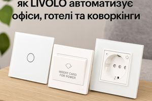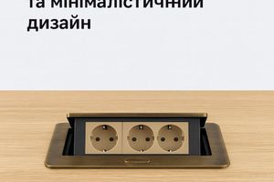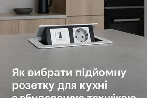
The correct designation of a socket on a diagram is essential, as it directly affects the design process and, subsequently, the installation of electrical networks. Specific symbols indicate the location and even the type of socket. This allows for a safe layout according to regulatory requirements, ensuring user safety in the future.

General Information on Socket Designation in Diagrams
Electrical diagrams—whether schematic, wiring, or functional—are essentially blueprints of an electrical installation. Each element has a clear and standardized symbol that makes it easy to understand the function of each component and enables accurate installation.
The socket is represented on the diagram by a specific graphic symbol. These are standardized and understood by both professionals and those new to the field.
Understanding exactly where grounded sockets are placed and where waterproof ones are located helps to quickly and accurately interpret project documentation. This ensures proper installation without overloads or short circuits. In other words, socket designation on diagrams also plays a role in planning the layout of household appliances, lighting elements, and all other electrical devices in a room.
Standards and Norms for Socket Designation
In electrical engineering, there are international and national standards that regulate socket designation. This applies to modern models such as WiFi smart sockets, pop-up sockets, and network sockets. One of the key international standards is IEC 60617, which includes unified symbols for all main elements in electrical diagrams, including sockets.
A standard power socket is usually represented as a circle or square with two parallel lines. Additional details are often included with the symbol, such as:
- Number of poles;
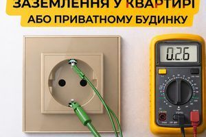
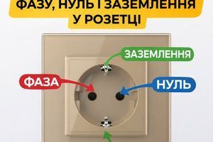
- Presence of grounding;
- Degree of moisture protection.
Letter or numerical codes are added to the symbols to maintain clarity, regardless of the country in which the diagrams are created.
Methods of Socket Designation on Diagrams
Let’s take a closer look at how sockets are represented on diagrams using standard symbols:
- A regular single-phase universal socket is shown as a circle or square with two parallel lines;
- Grounded sockets include a third line and the symbol “G”;
- Double sockets are shown with two connected symbols;
- Sockets with additional features, such as combo sockets, include extra identifiers (e.g., USB);
- Installation height can be noted beside the symbol, such as “R1-0.3,” indicating that socket 1 is installed 30 cm from the floor.
These simple symbols create optimal conditions for fast, high-quality, and safe electrical wiring installation along walls.
Flush-Mounted and Surface-Mounted Sockets: Symbol Conventions
Since there are various types of sockets, including by installation method, diagrams also account for this. Flush-mounted models are installed within the wall, with only the faceplate visible. These are more aesthetically pleasing and safer. On diagrams, they may use standard symbols with additional markings such as “F” (flush) or “IW” (in-wall).
Surface-mounted sockets are installed on the wall surface and are used where flush installation is not possible. Additional symbols for these include “S” for surface-mounted or “OM” (open-mounted). Sometimes, a bold outline is used to indicate a protruding installation.
Waterproof Sockets in Diagrams
Moisture exposure is very dangerous for sockets, so special markings are required in diagrams where such risks exist. The basic symbol remains, but an IP index is added to indicate the level of moisture protection. For instance, IP44 protects against splashes, while IP55 protects against water jets under pressure. The installation type can also be specified as discussed earlier.
Color Coding in Diagrams
This is an additional identification element used for easier diagram reading, especially in digital design software. It simplifies visual perception. Examples include:
- Blue — 220V socket;
- Red — socket with dedicated power supply, e.g., for critical devices;
- Green — grounded socket;
- Yellow — temporary or technical socket.
QR codes, numerical identifiers, and other additional labels can also be used.
Practical Use of Symbols and Diagram Errors
The importance of standardized socket symbols in diagrams cannot be overstated. Knowing which socket is installed where helps:
- Accurately calculate load;
- Prevent breaker overloads;
- Ensure convenient appliance placement;
- Simplify future maintenance.
However, even with standardized notation, errors can occur. These may lead to installation issues, safety code violations, short circuits, or reduced reliability of the electrical network. To prevent such problems, it is vital to follow current standards and review diagrams before installation. When in doubt, consult a professional.